- All
- Product Name
- Product Keyword
- Product Model
- Product Summary
- Product Description
- Multi Field Search


Views: 0 Author: Site Editor Publish Time: 2026-07-02 Origin: Site


Uneven loop heights instantly degrade the visual and structural quality of a tufted textile, turning premium designs into factory seconds. When operating a Plain Loop Tufting Machine, achieving uniform texture requires precise mechanical synchronization across multiple components. In commercial and high-end prosumer manufacturing, inconsistent pile height leads to material waste, increased quality assurance rejection rates, and compromised durability. A single skipped stitch or a millimeter of mechanical play can ruin an entire production run.
Controlling this consistency relies on strict mechanical calibration. The interaction between the needle stroke, looper timing, yarn tension, and backing advancement dictates the final surface texture. This guide breaks down exactly how a plain loop tufting machine controls loop height, the calibration required for straight stitch consistency, and how to evaluate machine capabilities for scalable production.
Consistent loop height relies on the precise synchronization of needle stroke depth, glide foot height, looper timing, and yarn feed tension.
Unlike cut pile machines, a plain loop tufting machine requires stricter backing tension control to prevent yarn pull-out during the needle's upward stroke.
Evaluating a machine for commercial loop pile carpet production requires assessing the rigidity of its looper mechanism, the clearance tolerances between needle and looper, and the granularity of its stroke adjustments.
Routine maintenance, specifically consistent lubrication of the needle bar and looper shaft, is non-negotiable for preventing motor strain and erratic stitch lengths.
The continuous yarn feed mechanism specific to loop pile creation relies on an uninterrupted flow of material. The mechanical sequence begins with needle penetration, driving the yarn through the primary backing cloth. Immediately after reaching the bottom dead center of the stroke, the looper engages. This small metal hook crosses the needle scarf, catching and holding the yarn loop in place. As the needle retracts upward, the backing advances, and the looper eventually releases the previous loop to catch the next one.
The absence of a cutting scissor mechanism fundamentally changes the tension dynamics compared to cut-pile machines. Without blades severing the yarn to release tension, all mechanical responsibility shifts to the looper and the backing grip. The yarn remains a continuous strand. If the backing material flexes or the looper releases the yarn a fraction of a second too early, the loop will pull right back out, resulting in a flat spot or an uneven surface.
Critical timing between the needle and the looper dictates the success of every single stitch. When the needle reaches its lowest point, the looper must cross the needle scarf at the exact right millisecond. The clearance tolerance required between the looper hook and the needle is exceptionally tight, typically ranging from 0.1mm to 0.2mm. This microscopic gap prevents the looper from physically striking the needle while ensuring it reliably catches the yarn.
Micro-deviations in this timing cause skipped stitches, split yarn, or varied loop sizes. If the looper is too far back, it misses the yarn entirely. If it is too close, it causes friction, heat buildup, and eventual component failure. Maintaining this synchronization requires rigid machine construction and frequent calibration checks, especially after changing pile height settings.
Component | Function in Loop Pile | Calibration Tolerance |
|---|---|---|
Needle | Punches yarn through backing | Stroke depth dictates max height |
Looper Hook | Catches and holds the loop | 0.1mm - 0.2mm clearance from needle |
Glide Foot | Holds backing flat during stroke | Must match needle stroke depth exactly |
Yarn Feed | Supplies continuous yarn strand | Consistent tension required |
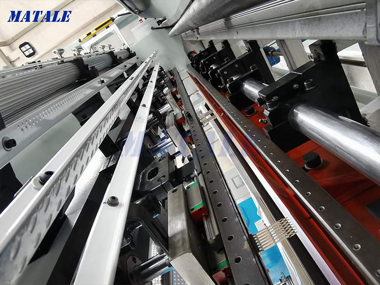
The physical distance the needle travels through the primary backing dictates the maximum potential loop height. A longer stroke pushes more yarn through the cloth, creating a taller loop. However, adjusting the needle stroke alone is insufficient without adjusting the height of the glide foot, also known as the front foot, to match. This is a common calibration bottleneck that frustrates many operators.
Calibrating the eccentric bearing or stroke linkage locks in a specific pile height. Simultaneously, you must adjust the glide foot to prevent backing compression. If the needle stroke is set for a high pile, but the glide foot remains low, the foot will physically block the backing from releasing the loop properly, or it will crush the loops as the machine moves forward. The foot must rest firmly against the backing to prevent bouncing, but not so tight that it restricts movement.
Disconnect power to the machine before making any mechanical adjustments.
Loosen the eccentric bearing lock nut to adjust the needle stroke depth.
Rotate the main shaft manually to ensure the needle reaches the desired bottom dead center.
Adjust the glide foot bracket so the foot rests flush against the backing material without compressing it.
Tighten all lock nuts and manually cycle the machine to verify clearance.
Yarn delivery speed directly impacts loop formation. The yarn must flow off the cone smoothly and continuously. Excessive tension causes tight or shallow loops because the machine fights the resistance, pulling the yarn back through the backing during the upward stroke. Conversely, insufficient tension leads to sloppy, oversized loops, yarn bunching, and tangles within the feed mechanism.
Automated yarn feed systems become a necessity in large-scale loop pile carpet production. These systems regulate the delivery speed, ensuring that the exact amount of yarn required for the set pile height is fed to the needle for every stitch. Relying on manual unwinding or passive tensioners often introduces variables that manifest as high-low texture variations across the finished textile.
The speed at which the backing cloth moves past the needle dictates stitch density. There is a direct correlation between stitch density and perceived loop height. Overcrowding forces loops upward, making the pile feel denser and slightly taller. Sparse stitching allows loops to lay flat, exposing the backing and reducing the overall height profile.
You must maintain 100% drum-tight backing tension to prevent the cloth from flexing during needle penetration. If the fabric bounces, the effective stroke depth of the needle changes with every stitch. This bouncing directly causes erratic loop heights. Stretching the primary backing properly on the frame and ensuring the feed rollers grip it securely are foundational steps before turning on the machine.
Cut pile releases tension upon cutting; loop pile maintains continuous tension on the yarn strand. This fundamental difference makes loop pile highly sensitive to variations in backing tightness and yarn elasticity. When a cut pile machine snips the yarn, the tuft is left in the backing, free from the pull of the yarn cone. A loop pile machine pulls the next stitch from the same continuous strand, meaning any resistance up the line affects the loop currently being formed.
Eliminating the scissor mechanism removes the common issue of cut-pile height variation caused by dull or misaligned blades. However, it heightens the risk of yarn pull-out. The looper must hold the yarn securely while the needle retracts, and the backing must grip the yarn tightly enough to prevent the next downward stroke from pulling the previous loop flat.
Convertible cut-and-loop tufting guns often suffer from mechanical compromises. Loose conversion brackets, shifting looper heads, and shared drive shafts introduce microscopic play into the system. While versatile, these machines struggle to maintain the strict tolerances required for perfectly uniform loop heights over long periods.
Commercial-grade operations favor a dedicated straight stitch loop machine to achieve ultra-granular, high-density detailing without the risk of loose mechanical play. A dedicated machine features a fixed looper assembly and a reinforced needle bar, eliminating the structural weaknesses inherent in convertible models. This rigidity translates directly to consistent pile heights.
Adjusting loop heights to create granular, sculptured, or 3D details is a popular production technique. However, there are significant mechanical trade-offs and risks involved in frequently altering stroke depth on a single machine. Constantly changing the eccentric bearing settings increases wear and tear on the linkage components.
Attempting a 3D effect by manual machine manipulation during a run often leads to irregular stitch spacing and structural instability. For scalable production, utilizing multi-pile height tufting setups or automated machines designed specifically for variable pile heights is far more reliable than manually tweaking a standard machine mid-production.
When inspecting a finished piece, alternating high and low loops indicate a mechanical or feed issue. Root causes typically include uneven yarn cone unwinding, fluctuating pneumatic pressure, a loose needle bar, or a worn looper hook tip. If the yarn snags on the cone, the sudden tension pulls the loop short.
Mitigation steps involve standardizing yarn delivery paths. Ensure the yarn feeds through all eyelets smoothly without sharp angles. Check for mechanical play in the driving gears; if the needle bar wiggles side-to-side, the bearings require replacement. Inspect the looper hook for burrs or dullness that might catch the yarn inconsistently.
Symptom | Likely Cause | Immediate Fix |
|---|---|---|
Alternating high/low loops | Uneven yarn tension from cone | Rethread yarn path, check for snags |
Skipped stitches | Looper clearance too wide | Adjust looper to 0.1mm-0.2mm from needle |
Loops pulling out | Loose backing material | Restretch backing drum-tight on frame |
Motor straining | Glide foot set too low for stroke | Raise glide foot to match needle depth |
Skipped stitches occur when the looper fails to retain the yarn during the needle's upward stroke. This usually points to improper synchronization or excessive clearance between the needle and the looper. If the gap is wider than 0.2mm, the looper will occasionally miss the yarn loop entirely.
Using incorrect backing materials also exacerbates this issue. A weave that is too loose will not grip the yarn sufficiently. Polyester backings with high elasticity can stretch during penetration and rebound, pulling the loop out. Standardizing on a rigid, industry-standard primary tufting cloth provides the necessary grip to hold loops securely.
Operators often encounter a fixed-height issue where adjusting the eccentric wheel fails to increase loop size. This happens because the glide foot is physically blocking the backing from releasing the loop. The needle pushes the yarn deep, but the foot crushes it flat against the backing plate.
To resolve glide-foot height limitations, follow a strict calibration sequence. First, set the needle stroke to the desired depth. Next, manually rotate the machine to the bottom dead center. Finally, loosen the glide foot bracket and adjust it so it rests lightly against the backing material without compressing it. Lock the bracket securely before resuming operation.
Electronic warnings, such as beeping, or sluggish motor performance indicate mechanical binding or a needle-to-looper collision. These are critical warnings that must not be ignored. If the machine sounds strained, components are rubbing together incorrectly.
Friction points that cause motor strain often occur when loop height settings are pushed beyond the machine's rated capacity. Pushing a machine designed for a maximum 12mm pile to 18mm causes the linkage arms to overextend, binding the drive shaft. Always operate within the manufacturer's specified pile height range.
When evaluating a plain loop tufting machine, inspect the rigidity of the looper hook and needle bar assembly. These components handle the highest stress loads. Flimsy stamped metal parts will flex under tension, leading to immediate height inconsistencies.
Heavy-duty bearings are critical for maintaining consistent stroke depth over long production runs. Sealed bearings prevent dust and yarn fibers from entering the moving parts, ensuring the stroke remains smooth and accurate month after month.
Evaluate how easily operators can adjust pile height and stitch rate without requiring complete machine teardowns. Time spent calibrating is time lost in production. Machines that require disassembling the entire front housing to reach the eccentric bearing are inefficient for operations that change pile heights frequently.
Compare manual hex-key adjustments versus digitized stroke controls in industrial models. While manual adjustments are standard and reliable, they require a skilled operator to achieve exact tolerances. Digitized controls offer precise, repeatable settings, reducing setup time and minimizing human error.
Baseline maintenance is required to keep tolerances tight. Regular application of sewing machine oil to the needle bar, looper shaft, and gear mesh is mandatory. Metal-on-metal friction generates heat, causing components to expand and tolerances to shift.
Neglected maintenance directly translates to erratic loop heights due to component wear, heat expansion, and friction-induced deceleration. A dry machine runs slower, pulls harder on the yarn, and eventually seizes. Establish a strict lubrication schedule at the start of every shift.
Clean lint and yarn dust from the looper assembly daily.
Apply two drops of oil to the needle bar shaft before every shift.
Inspect the looper hook for burrs or dull edges weekly.
Check the eccentric bearing lock nuts for tightness monthly.
Audit your current yarn delivery system to eliminate tension bottlenecks and ensure smooth unwinding.
Standardize your primary backing material to a rigid, low-stretch fabric to improve yarn grip.
Establish a strict, step-by-step calibration protocol for matching glide foot height to needle stroke depth.
Implement a daily lubrication schedule for the needle bar and looper shaft to prevent friction-induced tolerance shifts.
A: Loops pull out when the backing material is not stretched drum-tight on the frame, if the looper mechanism fails to hold the yarn long enough during the needle's retraction, or if the yarn tension is too high, pulling the loop back through the backing.
A: Lubricate the needle bar, looper shaft, and moving gears at the start of every production shift. Use a high-quality sewing machine oil to prevent friction, heat expansion, and component wear.
A: Yes, by adjusting the needle stroke depth and glide foot height, you can create different pile heights. However, frequently changing these settings manually during a single run can lead to mechanical instability and inconsistent spacing.
A: Beeping or sluggish motor performance indicates mechanical binding, excessive friction, or a needle-to-looper collision. Stop immediately, unplug the machine, and check for tangled yarn, lack of lubrication, or misaligned components.
A: The ideal clearance tolerance between the needle and the looper hook is typically between 0.1mm and 0.2mm. This ensures the looper catches the yarn without striking the needle.
A: If you increase the needle stroke but the loop height does not change, the glide foot is likely too low. It is physically blocking the backing from releasing the longer loop. Adjust the glide foot upward to match the new stroke depth.
A: For commercial production, yes. Dedicated loop machines feature rigid, fixed components that maintain tight tolerances. Convertible machines often have loose brackets and mechanical play that lead to inconsistent loop heights.