- All
- Product Name
- Product Keyword
- Product Model
- Product Summary
- Product Description
- Multi Field Search


Views: 0 Author: Site Editor Publish Time: 2026-09-02 Origin: Site


In commercial broadloom and carpet tile manufacturing, production profitability hinges on the exact, repeatable execution of complex designs. Facility managers and interior designers demand flawless visual continuity across massive floor plans. Inconsistent pattern repeats cause severe alignment issues during installation. This leads to high rates of material waste, rejected batches, and compromised aesthetic quality in large-scale commercial deployments. Achieving pixel-perfect consistency requires moving beyond basic mechanical setups.
Evaluating a modern graphic loop tufting machine requires a deep understanding of internal mechanics. Buyers must analyze how servo-driven yarn feeds, shifting needle bars, and digital mapping software interact. These components must work in perfect synchronization to control pattern repeats at high production speeds.
Pattern repeats are primarily controlled by the synchronization of servo yarn feed systems that dictate exact yarn tension and pile height for every individual stitch.
Lateral pattern generation relies on precision needle bar shifting mechanisms, requiring robust linear actuators to prevent mechanical drift over long production runs.
Digital pattern mapping software translates design files into machine code, but real-world accuracy depends on closed-loop encoder feedback to adjust for mechanical wear and yarn elasticity.
When evaluating equipment, buyers must weigh the trade-offs between maximum operating speed and the complexity of the pattern repeat, as high-frequency shifts naturally limit RPM.
The choice of carrier material (woven vs. non-woven backing) directly impacts the machine's ability to hold a strict pattern tolerance.
To evaluate a machine's capability to hold a tight pattern repeat, buyers must first understand the physical mechanisms responsible for yarn placement and pile height variation. Software commands fail if the physical hardware cannot execute them precisely. Mechanical rigidity forms the foundation of pattern accuracy. Without a stable mechanical baseline, digital systems constantly overcompensate, leading to erratic stitch placement and visible defects on the carpet face.
Before running any complex graphic pattern, operators must establish a rigid mechanical baseline. This involves several strict calibration steps:
Verify main shaft alignment using dial indicators to ensure zero runout during high-speed rotation.
Calibrate backing feed roller tension load cells to guarantee uniform pull across the entire width of the machine.
Inspect linear guide rails for scoring or inadequate lubrication, which introduces drag into the shifting mechanism.
Test individual servo motor response times via the diagnostic terminal to identify lagging drives.
Individual or grouped servo motors control the exact amount of yarn delivered to the needles. Older mechanical systems relied on complex cam profiles and clutches, which limited design flexibility and required hours of manual retooling. A modern servo yarn feed tufting machine replaces these physical limitations with infinite digital adjustability. These motors react instantly to software commands, adjusting rotational speed to match the required yarn length for the upcoming stitch.
Servo-driven rollers create high, medium, and low loops by dynamically altering yarn feed rates millisecond by millisecond. When the software demands a high loop, the servo accelerates the roller. This feeds excess yarn into the needle zone. Conversely, restricting the feed rate pulls the yarn tight against the looper, creating a low pile profile. This rapid acceleration and deceleration must happen without snapping the yarn or causing excessive tension spikes.
Assess the granularity of the servo control during equipment evaluation. Single-end control assigns a dedicated motor to each individual yarn end. This offers maximum pattern definition and absolute control over every pixel of the design. Scroll roll control groups multiple yarns onto a single driven roller. This limits individual stitch precision but significantly simplifies the mechanical setup and reduces maintenance overhead. The choice depends entirely on the required pattern resolution and the facility's maintenance capabilities.
Sliding needle bars move laterally across the backing material to create complex designs. These bars hold hundreds of needles in precise alignment. By shifting left or right between stitches, the machine breaks up the linear rows typical of basic tufting. This lateral movement allows the creation of curves, angles, and intricate geometric shapes within the loop pile.
The combination of lateral shifting and longitudinal backing feed creates the geometric foundation of the pattern repeat. As the backing material moves forward through the machine, the needle bar shifts horizontally. The synchronization of these two axes dictates the exact placement of every yarn tuft. Any hesitation in either axis distorts the final image, turning a perfect circle into a jagged oval.
Look for machines utilizing high-precision linear guides and direct-drive actuators. These components minimize the mechanical backlash that causes pattern distortion. Backlash is the slight mechanical play between moving parts. Over a long production run, even a fraction of a millimeter of backlash compounds into visible pattern drift. Direct-drive systems eliminate intermediate linkages, ensuring the needle bar stops exactly where the software commands.
Maintaining absolute, uniform tension on the primary backing fabric is strictly necessary. This fabric acts as the carrier material for the entire tufted structure. It moves continuously through the tufting zone, pulled by spiked rollers. If the tension varies across the width of the machine, the pattern will warp. The feed rate must remain perfectly constant regardless of the needle penetration force.
Different carrier webs interact uniquely with needle penetration and affect dimensional stability. Woven polypropylene offers high tensile strength and resists tearing. However, its rigid grid structure can deflect needles slightly upon entry, causing minor stitch irregularities. Non-woven polyester provides a more uniform surface. It allows for smoother needle penetration and better dimensional stability, making it ideal for highly detailed graphic patterns.
Even minor fluctuations in backing tension can elongate or compress the pattern repeat. This ruins tile-to-tile matchability. If the tension spikes, the backing stretches. The machine tufts the pattern into a stretched canvas. When the tension releases, the backing shrinks, compressing the pattern. This makes it impossible to align carpet tiles during installation, resulting in massive material rejection rates.
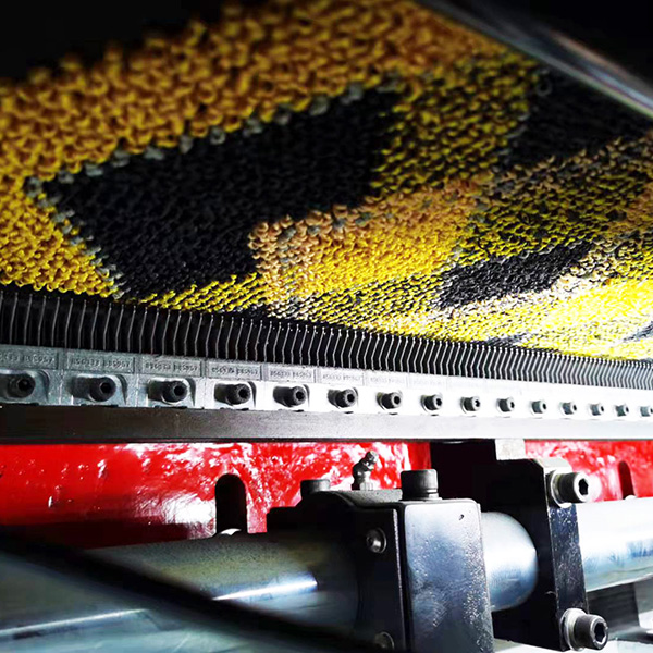
Modern tufting relies entirely on digital interfaces rather than mechanical cams. The software acts as the brain, translating artistic designs into precise mechanical movements. Understanding this translation process is required for troubleshooting pattern defects on the factory floor.
CAD software translates raster or vector designs into specific machine commands. Designers create patterns using standard graphic formats. The tufting software overlays a grid onto this design. Each pixel on the grid corresponds to a specific stitch rate, pile height, and lateral shift distance. The software compiles this data into a continuous stream of execution codes for the servo motors.
The machine's onboard processor must handle high-density data without buffering delays. Complex graphic loops require millions of calculations per minute. A 1000x1000 pixel bitmap translates to one million individual stitch commands. If the processor lags, the physical machine must wait for instructions. This causes micro-stutters in the backing feed or needle stroke. These stutters manifest as visible horizontal lines or pattern glitches in the finished carpet.
Rotary and linear encoders monitor the actual physical position of the main shaft, needle bars, and backing feed rollers. Encoders are precision sensors that track movement. They provide a constant stream of positional data back to the central processor. This data confirms whether the mechanical parts actually moved to the commanded positions.
The system uses this real-time data to micro-adjust the servo components. This closed-loop feedback maintains the mathematical pattern repeat. It automatically compensates for mechanical wear, temperature fluctuations, and yarn elasticity. If an encoder detects that the backing feed roller slipped by a tenth of a millimeter, the processor instantly adjusts the yarn feed rate to match the actual backing position, preventing pattern distortion.
Component Monitored | Encoder Type | Failure Symptom | System Correction Action |
|---|---|---|---|
Main Drive Shaft | Absolute Rotary | Needle timing mismatch | Adjusts servo feed timing to match shaft angle |
Needle Bar Shifter | High-Res Linear | Jagged diagonal lines | Micro-corrects actuator position before next stroke |
Backing Feed Rollers | Incremental Rotary | Pattern elongation/shrinkage | Alters roller RPM to maintain constant fabric tension |
Yarn Feed Servos | Integrated Motor Encoder | Inconsistent pile height | Increases/decreases torque to overcome yarn drag |
Frameworks for comparing different machine models must focus on production outcomes rather than just spec sheets. Theoretical speeds often fail to translate into real-world efficiency. Buyers must evaluate equipment based on its ability to sustain strict tolerances under continuous industrial operation.
Acceptable industry tolerances for pattern elongation or shrinkage are extremely tight. Over a standard roll length of 100 feet, the pattern variance must typically remain under half an inch. Exceeding this tolerance makes pattern matching at the installation site impossible. The machine must hold this tolerance consistently, day after day, across varying environmental conditions and yarn lots.
Test a machine's ability to hold a strict repeat across the full width of the needle bed. Edge-to-edge consistency is a primary indicator of machine quality. If the pattern is accurate in the center but distorted at the edges, the needle bar lacks structural rigidity. It also indicates uneven tension on the backing material feed rollers. Demand physical samples taken from both edges and the center of a test run to verify structural integrity.
Evaluate whether the production line requires a dedicated loop machine or a Level Cut Loop (LCL) system. Dedicated loop machines are highly efficient and mechanically simpler. LCL systems integrate cut pile elements for advanced modern aesthetics. They offer superior design flexibility but require significantly more maintenance and careful calibration.
Analyze the added mechanical complexity required when a patterned loop carpet machine is also tasked with producing cut pile textures. Looper and knife timing synchronization becomes the most critical adjustment on the machine. A looper catches the yarn, and a synchronized knife blade slides against the looper to cut it. The system must selectively cut certain loops while leaving others intact, all at high speeds. Misaligned knives will fray the yarn, dull against the looper, or fail to cut entirely, ruining the textural contrast of the design.
Analyze the inverse relationship between machine RPM and the frequency of needle bar shifts. You cannot run highly complex patterns at maximum machine speeds. Wide lateral shifts require the needle bar to travel further between strokes. The main shaft must slow down to give the shifting mechanism enough time to reach its target position before the needles penetrate the backing.
Highly complex, multi-pile-height graphic loops require lower operating speeds to prevent yarn breakage and mechanical fault. Forcing the machine to run faster than the pattern allows will snap yarns, bend needles, and trigger automatic stops. This downtime negates any perceived speed advantage.
Pattern Type | Shift Frequency | Pile Height Variation | Optimal Production Speed |
|---|---|---|---|
Basic Linear Loop | Zero (Straight Stitch) | Uniform | High (Max RPM) |
Simple Geometric | Low (1-2 steps) | High/Low Dual | Medium-High |
Complex Organic Graphic | High (Multi-step wide shifts) | Multi-level (Infinite) | Medium-Low |
Intricate LCL Graphic | High | Mixed Cut and Loop | Low (Requires knife timing) |
Evaluate the efficiency of the machine's threading process and digital pattern changeover capabilities. Threading thousands of needles manually is labor-intensive. Machines designed with ergonomic yarn routing and accessible needle bars reduce downtime significantly. Digital changeovers should require only a few clicks at the control terminal, loading new tension profiles instantly without mechanical retooling.
Assess how quickly the machine achieves a stable pattern repeat at the start of a new roll. Minimizing "head-end" waste is required for profitability. Some machines require several yards of tufting before the backing tension stabilizes and the pattern aligns. Advanced systems use pre-tensioning algorithms to ensure the very first inch of carpet meets strict dimensional tolerances, saving thousands of dollars in wasted yarn and backing over a year.
Address the operational realities and maintenance challenges that threaten pattern integrity post-purchase. Even the most advanced tufting machines suffer from pattern drift if poorly maintained. Proactive management of the yarn supply and mechanical wear prevents costly production errors.
Variations in yarn tension originating from the creel will distort the pattern before the yarn even reaches the servo feeds. The creel holds the yarn cones. If one cone unwinds with more resistance than another, the servo motor must work harder to pull it. This alters the final pile height of that specific stitch, creating visible streaks in the carpet.
Specify the need for advanced creel tensioning devices and regular calibration of the yarn path. Operators must verify tension uniformity across the entire creel before starting a complex graphic run. Implement the following creel management steps:
Install anti-static yarn routing tubes across the entire creel structure to prevent friction buildup.
Utilize pneumatic tensioners to apply uniform drag to every yarn end.
Conduct weekly pull-tests using a digital tension meter to identify failing tensioners.
Replace worn ceramic eyelets immediately to prevent yarn fraying and snapping.
Continuous high-speed operation degrades the friction surfaces of yarn feed rollers and introduces play into shifting mechanisms. The abrasive nature of carpet yarn slowly wears down the grip coating on the servo rollers. Once the roller loses grip, the yarn slips. The servo motor turns, but the correct amount of yarn is not delivered, destroying the pattern repeat.
Establish a strict preventative maintenance schedule focusing on roller resurfacing and actuator lubrication. Do not wait for pattern defects to appear on the inspection frame. Replace or recoat feed rollers at specified hourly intervals. Keep linear guides heavily lubricated to prevent metal-on-metal wear. Evaluate vendors based on replacement part availability and local service support.
Operators accustomed to mechanical adjustments may struggle to troubleshoot software-driven pattern drift. In older machines, fixing a pattern meant turning a wrench or adjusting a cam. In modern graphic tufting, fixing a pattern requires analyzing encoder logs and adjusting digital tension profiles. This requires a completely different skill set.
Mandate comprehensive vendor-supplied training on the specific CAD-to-machine software environment. Operators must understand how to read error codes and interpret sensor data. They need to know how to adjust pixel-to-stitch mapping on the fly. Investing in operator education directly reduces machine downtime and prevents catastrophic material waste.
A graphic loop tufting machine's ability to control pattern repeats relies entirely on the integration between its digital mapping software, its physical servo yarn feeds, and the dimensional stability of its carrier material. Mechanical rigidity provides the foundation. Precise servo control executes the design. Closed-loop feedback ensures long-term accuracy. Without all three elements working in harmony, pattern drift is inevitable.
Prioritize manufacturers that offer closed-loop encoder feedback, robust linear actuators for needle shifting, and transparent data on repeat tolerances at maximum operating speeds. Look past theoretical maximums and focus on sustained, real-world performance metrics.
Request a live demonstration running your specific, highly complex pattern files to verify repeat accuracy and backing tension stability.
Audit the machine's software interface with your design team to ensure they can execute pixel-to-stitch conversions without third-party software.
Establish a strict preventative maintenance baseline for servo feed rollers and linear actuators immediately upon installation.
Implement mandatory digital troubleshooting training for all lead machine operators before beginning commercial production.
A: Mechanical scroll machines use physical cams, clutches, and gears to pull yarn, limiting designs to fixed repeat lengths. A servo yarn feed tufting machine replaces these with individual, software-controlled servo motors. This allows for precise yarn delivery, infinite pattern flexibility, and instant digital changeovers without swapping mechanical parts.
A: Pattern drift is typically caused by inconsistent backing tension, which stretches or compresses the fabric. Other culprits include yarn elasticity variations from the creel, mechanical wear causing backlash in the needle bar shifter, or encoder failure failing to report accurate positional data to the processor.
A: Pile height is controlled digitally by the servo yarn feed rollers. The rollers accelerate to feed excess yarn for high loops and decelerate to restrict yarn for low loops. This action is perfectly synchronized with the needle stroke and looper engagement to form the exact required height millisecond by millisecond.
A: Yes, the machine produces continuous roll goods suitable for both. However, the strictness of the pattern repeat control dictates success. Carpet tiles require absolute dimensional stability and flawless pattern repeats so that individual squares align perfectly during installation. Broadloom is slightly more forgiving regarding minor pattern elongation.
A: Dedicated loop machines cannot. However, Level Cut Loop (LCL) machines utilize specialized loopers equipped with synchronized knives. These systems convert specific loops into cut pile based on software commands. This offers greater textural versatility but comes at the cost of significantly higher mechanical complexity and maintenance.
A: While basic tufting machines can exceed 1000 RPM, complex graphic loops typically run between 400 and 700 RPM. Maximum speed drops significantly when executing wide lateral needle bar shifts or frequent high/low pile transitions, as the mechanical components need time to reach precise target positions.
A: Lateral needle bar movement breaks up the standard linear rows of tufting. By shifting left or right between stitches, the machine can place yarn diagonally. This allows designers to create smooth curves, sharp angles, and complex geometric shapes in the loop pile, moving beyond simple straight-line textures.